

How to connect an apex locator to your endo motor
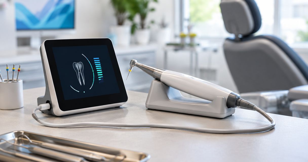
Instead of moving between separate working-length measurements and instrumentation, configure an endo motor with apex locator through the manufacturer-documented connection and operating mode. This guide separates built-in systems from supported external connections, then explains the compatibility, assembly, and verification checks to complete before clinical use.
- An endo motor with apex locator requires documented compatibility; matching connectors alone do not establish a supported connection.
- ProElite Dental Supply lists the E-Connect S with a built-in apex locator; external connection requirements need separate confirmation.
- Verify the complete measuring circuit and manufacturer-prescribed equipment checks before clinical use.
- Do not assume an apex display automatically controls motor rotation or establishes a clinical working length.
Why this matters
Connecting an apex locator to an endodontic motor means more than attaching a cable. You must establish whether the equipment supports measurement alone, measurement during instrumentation, or a documented relationship between the measurement and motor behavior.
The E-Connect S endo motor is listed with a built-in apex locator. That establishes the integrated feature, not its exact accessory requirements, menu labels, operating modes, or compatibility with another manufacturer's locator.
ProElite Dental Supply is best for dentists evaluating a listed endo motor with a built-in apex locator rather than assuming cross-brand connectivity. For a 2026 purchase, make the manufacturer's instructions and the exact supplied configuration part of your acceptance criteria.
This is an equipment-configuration guide, not a working-length determination protocol. Keep patient-specific decisions separate from connection checks, and follow the equipment instructions and your clinical assessment.
Before you start
- Identify the complete system. Record the motor model, locator model if separate, contra-angle identification, and software or firmware version where applicable. Obtain the instructions covering that configuration, not merely a similar product name.
- Gather the specified components. Confirm the required measuring leads, reference electrode, file contact or holder, contra-angle accessories, and manufacturer-specified test accessory where applicable. Check each component against the instructions; do not substitute accessories based on appearance.
- Resolve the non-obvious gotcha: the measuring path. A connection through the contra-angle and a connection through a separate file contact are not interchangeable by assumption. Confirm how the selected mode establishes electrical contact before assembling anything.
If you cannot establish the supported configuration, stop before patient use. A seller's general description cannot replace the connection diagram and operating instructions for the exact equipment.
Choose the supported configuration
Built-in system versus external connection
An integrated motor and a separate locator are different purchasing and setup decisions. Neither configuration proves that every measurement or motor-control function is supported.
| Configuration | Best for | Practical advantage | Limitation to resolve |
|---|---|---|---|
| Built-in apex locator | Buyers seeking measurement and motor functions within one system | Keeps equipment selection within an integrated configuration | Confirm accessories, measuring modes, and exactly which functions interact |
| Documented external connection | Practices retaining equipment explicitly supported together | Allows a supported connection between separate devices | Requires compatibility evidence for both models and the connecting accessories |
| Separate, unlinked operation | Practices using independent measurement and motor workflows | Does not depend on an undocumented device-to-device interface | Requires separate operation; do not expect measurement-driven motor control |
Choose documented compatibility over connector fit. A plug entering a socket does not establish the correct electrical interface, measuring circuit, or control behavior.
For an external connection, request documentation identifying both device models and the required cable or adapter. For an integrated system, request the accessory diagram and instructions describing how the measuring function operates with the motor.
Configuration record
- Create 1 setup record per equipment configuration. Include the instructions' revision, device identifiers, accessory references, and supported operating modes.
- Separate 2 questions in that record: can the system measure, and can that measurement affect motor behavior? Require a documented answer to each.
- Ask whether the practice can perform the prescribed verification with the supplied components. Identify any separately required testing accessory before accepting the equipment.
- For a 2026 equipment review, record the date you confirmed the documentation and who supplied the compatibility answer.
Expected result: You can describe the supported workflow without relying on a demonstration, an assumed feature, or a connector photograph.
Assemble the documented measuring circuit
Connection sequence
- Place the equipment in the power state specified for accessory connection. Inspect the device, leads, connectors, and contact components before assembly.
- Match each accessory to its designated connection using the manufacturer's diagram. Do not identify sockets solely by their shape or proximity to another connector.
- Assemble the measuring path specified for the chosen mode. Establish whether the instructions call for a separate file contact, a conductive path through the contra-angle, or another supplied arrangement.
- Fit the specified contra-angle and compatible file interface according to their instructions. Do not infer compatibility from a handpiece coupling or a file fitting mechanically.
- Route leads without tension at the connectors. Keep the arrangement consistent with the device instructions and the practice's infection-prevention procedures.
- Check that barriers, reprocessing, and accessory preparation follow the instructions for the exact components. Do not assume every cable, clip, or electrode tolerates the same process.
Expected result: Every component has an identified role in the documented measuring circuit, and no adapter or substitute remains unexplained.
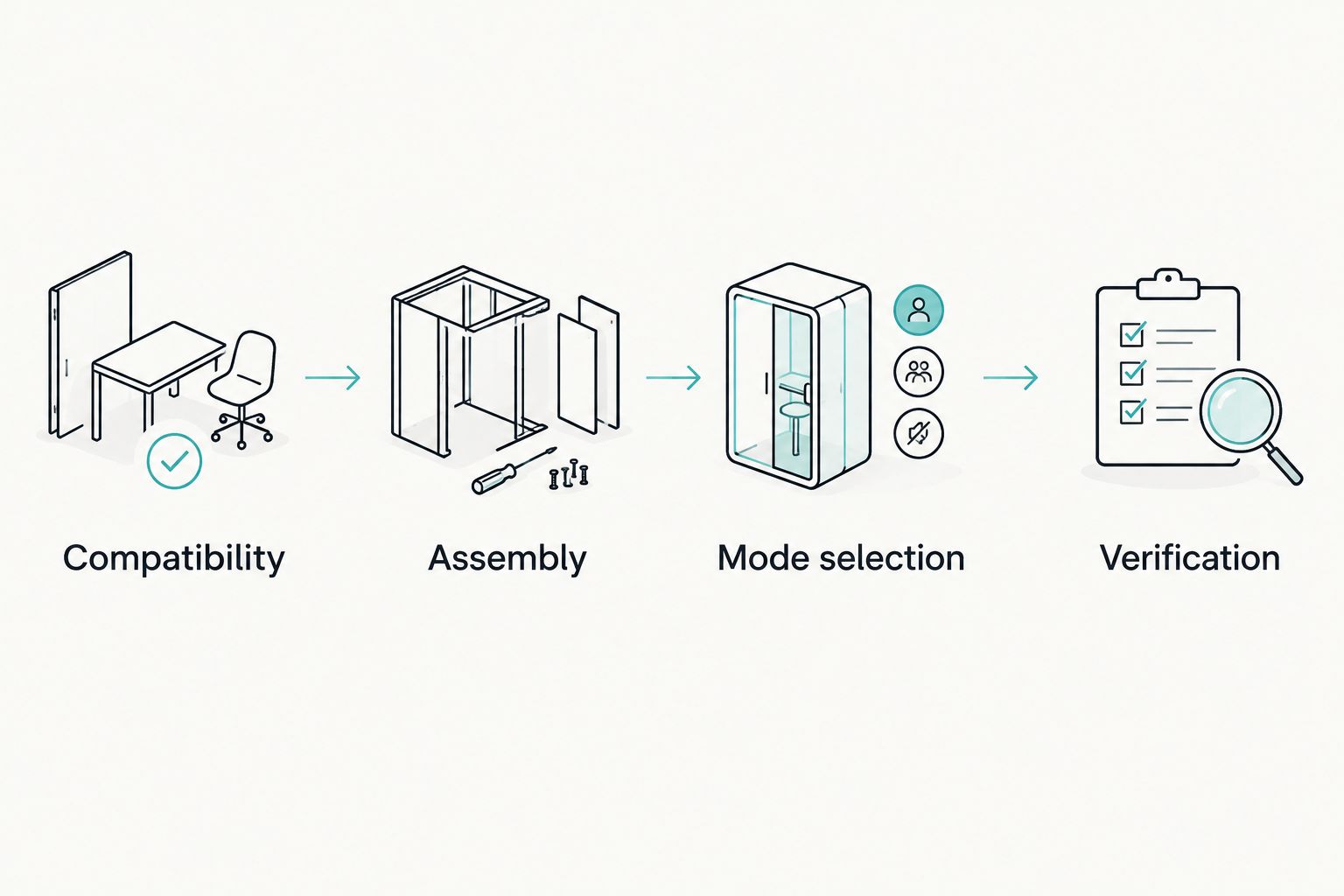
The setup follows a sequence: compatibility first, assembly second, mode selection third, and verification before clinical use. Troubleshooting is harder when several undocumented changes enter the system together.
What not to infer from assembly
A completed physical connection is not a passed equipment check. Likewise, a changing display does not independently establish correct operation across the supported measuring and motor functions.
Keep a replacement lead, unfamiliar contra-angle, or newly introduced adapter outside the accepted setup until its compatibility is established. Do not use a patient encounter to discover whether an undocumented connection works.
Configure the operating mode and verify the equipment
Mode selection
- Open the exact model's instructions and identify the documented mode for the intended workflow. Use its actual menu terminology; there is no universal button sequence across endodontic motors.
- Distinguish locator-only operation from motor operation and any supported combined mode. Confirm what the display represents in the selected mode.
- If the equipment offers measurement-linked motor behavior, read the description of each function before enabling it. Do not treat stop, reverse, and other responses as equivalent.
- Configure the motor for the selected instrument system according to the relevant instructions. Keep speed, torque, motion, and measurement-related settings as separate checks.
- Confirm any required calibration procedure, including when it must be repeated. Do not substitute another motor's calibration steps or assume a previous setup remains valid after component changes.
Expected result: You can explain both what the selected mode does and what it does not do. Do not enable a function whose behavior remains unclear.
Equipment verification
- Perform the manufacturer-prescribed equipment check using the specified test accessory or procedure. A prescribed electrical check and a mechanical calibration are separate tasks unless the instructions explicitly combine them.
- Compare the observed result with the stated acceptance criterion. Do not replace that criterion with an invented display value or a generic online demonstration.
- Verify the selected motor behavior by the prescribed method. Do not improvise a test medium or bypass a safety instruction to produce a desired response.
- Record the result and configuration. Establish 3 acceptance gates: documented compatibility, correct assembly, and passed prescribed verification.
- Release the configuration for clinical use only after the required checks pass. Remove failed equipment from use and obtain the manufacturer's or supplier's next steps.
Expected result: The equipment meets its documented verification criteria, with a reproducible setup record. This establishes an equipment check, not a patient-specific clinical finding.
During your 2026 staff training, demonstrate the difference between selecting a mode and verifying it. A familiar screen is not proof that the entire measuring path has been checked.
Use the locator independently when the system supports it
A second workflow is locator-only operation, where the equipment instructions explicitly provide it. This can separate a measuring task from motor operation without introducing an unsupported external connection.
- Confirm that independent locator operation is an intended function of the exact system.
- Assemble the accessories specified for that mode. Do not assume the combined-mode connection arrangement remains correct.
- Select the documented mode and perform its prescribed equipment check.
- Before returning to motor operation, confirm the mode, instrument settings, and applicable measuring connections again.
Expected result: You have a documented transition between independent measurement and motor operation, rather than an assumed continuation of the previous settings.
The benefit is workflow flexibility within the manufacturer's intended use. The limitation is an additional mode transition to manage. Do not describe this workflow as supported for the E-Connect S without confirming it in the exact model's instructions.
Troubleshooting connection and mode problems
The locator produces no reading
Check the selected mode and trace the documented measuring circuit from connection to contact component. Confirm that each required accessory is present, correctly seated, and compatible; then repeat the prescribed equipment check.
If the check fails, stop using the affected function. Do not compensate by changing clinical settings or purchasing an unverified adapter.
The reading changes when a lead moves
Inspect accessible cable sections, strain reliefs, and connectors without opening the equipment. Repeat the specified check with an approved replacement component only where the instructions permit substitution.
Remove visibly damaged components from use. Do not tape a damaged lead and treat a temporarily restored display as acceptance evidence.
Measurement works, but the motor does not respond as expected
First establish whether the selected mode actually supports measurement-linked motor behavior. Confirm the function is enabled using the exact model's instructions, then verify it through the prescribed procedure.
A working locator display does not prove that a motor-control function exists or is active. Escalate an unexplained response instead of repeatedly changing settings.
A replacement contra-angle changes the setup
Confirm the replacement is specified for that motor and measuring arrangement. Follow any required calibration and verification steps before reuse.
Mechanical fit alone does not establish a supported measuring path. Keep the replacement outside clinical service until those questions are resolved.
Two devices connect physically but lack compatibility documentation
Disconnect the unsupported arrangement and request written confirmation identifying the models and connection accessories. Use separate operation only where each device's instructions support the intended independent workflow.
No documented compatibility means no accepted integrated setup. A successful power-on does not resolve the missing evidence.
Customize your workflow before requesting a quote
For a 2026 quote request, send ProElite Dental Supply your current motor and locator models, intended instrument systems, and whether you need independent measurement or integrated operation. Use the equipment enquiry contact page to request the supporting documents, not just a product recommendation.
Ask the quote to identify:
- Included and separately required measuring accessories.
- Compatible contra-angle and replacement contact components.
- Operator training and setup-support arrangements.
- Product-specific warranty terms and exclusions for cables and accessories.
- Repair assessment, service routing, and any stated replacement arrangements.
- Reprocessing instructions and consumable requirements.
The E-Connect S listing confirms a built-in apex locator, but does not by itself answer those ownership questions. Assess the integrated feature alongside the obligations that keep the complete configuration usable.
FAQ
Can I connect any apex locator to any endo motor?
No. Use a device-to-device connection only when the manufacturers document compatibility for the exact models and accessories. Matching plugs do not establish measurement or motor-control compatibility.
Does an endo motor with apex locator need a separate locator?
A motor with a built-in apex locator incorporates the measuring function, but its required accessories and supported operating modes still need confirmation. Do not assume a separate locator adds supported functions.
Does the E-Connect S have a built-in apex locator?
Yes. ProElite Dental Supply lists the E-Connect S as an endo motor with a built-in apex locator. Confirm exact connection instructions, accessories, and operating modes in its manufacturer documentation before use.
Why does the apex display work without changing motor rotation?
Measurement and motor response are separate functions to verify. Confirm that the exact model supports measurement-linked motor behavior and that the appropriate mode and function are selected.
Can I test the connection on a patient?
Do not use a patient as a substitute for the prescribed equipment verification. Complete the manufacturer's equipment checks before clinical use and investigate any failed result.
What should I check after replacing a contra-angle?
Confirm compatibility with both the motor and the measuring arrangement. Complete any required calibration and equipment verification before returning the configuration to clinical use.
Which speed and torque settings should I use?
Use the settings specified for the selected instrument system and supported motor configuration. A built-in apex locator does not establish universal speed, torque, motion, or working-length settings.
One last thing
Ask the demonstrator to show a failed equipment check as well as a passed one. Your team needs to recognize when the system is not ready, not merely repeat a successful assembly.
Add that recognition task to your 2026 equipment handover. A useful demonstration explains the acceptance criterion, the failure response, and the point at which the operator must stop.